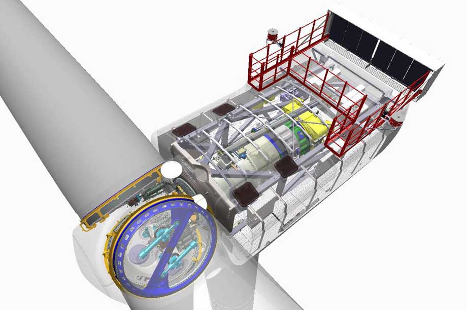
A combination of an 8MW power-rating and a 164-metre rotor diameter will make the V164-8.0 the world's most powerful turbine. A 2MW-class nacelle parked in another corner of the hall looked tiny in comparison with a massive V164-8.0 main shaft housing for a second prototype awaiting assembly. Everything is of a grand scale with this turbine, like the nacelle and hub with its massive pitch bearings and two long hydraulic pitch cylinders inside each blade-mounting area.
Despite industry-record specifications, the nacelle has a width and height of 8 metres and is "only" 20 metres long. This is enabled by a compact tube-shape medium-speed drivetrain. This in essence self-supporting structure incorporates a main shaft housing that serves as a key structural and drivetrain element mounted directly to a mass-optimised cast main chassis.
The main shaft supported by two bearings is attached to the rotor hub in front and faces rearwards. It is connected to the planetary gearbox and permanent magnet generator via a flexible shaft coupling. The four individual drive elements are connected through bolted-flanges. Flanged connections as a key benefit virtually eliminate misalignment risks, while a flexible shaft coupling in between the main shaft and gearbox plus generator in principle transmits only "pure" rotor torque into the gearbox. During our visit only the disk-shaped generator was awaiting assembly.
Structurally, Vestas chose a cast main chassis to sit beneath the nacelle cover. This comprises a horizontal and vertical cast section, instead of a commonly-used bell-shape cast main carrier. The chassis' horizontal section is mounted atop a yaw bearing operated by ten yaw motors. It serves together with the vertical section as an elements attachment base and also forms an integral part of the space frame that extends to the nacelle rear. The space frame is characterised by a series of interconnected square-tube elements all arranged in both vertically and horizontally oriented triangles around the drivetrain assembly. Benefits include a combination of high stiffness and strength, while optimising the nacelle mass and the elimination of a traditional separate generator chassis. The combined mass of a V164-8.0MW nacelle + hub is approximately 390 tonnes, and the mass of individual blades about 34 tonnes, resulting in around 500-tonne head mass.
Regarding electric power conversion, 710V generator alternate current (AC) power is fed into a (AC/DC) rectifier located in the nacelle rear, where direct current (DC) power feeds down the tower to an inverter (DC/AC conversion) in a tower-foot based E-module. The 14-metre high E-module incorporates the internal power supply cabinets at the third top level, the inverter (line side) at the second floor, followed by the transformer on the first floor. The bottom part of the tower contains the switchgear. A split rectifier/inverter solution positively impacts head mass compared with a converter located in the nacelle, as is the case with the company's 2MW and 3MW turbine platforms, according to Vestas chief technical officer Anders Vedel.
The nacelle cover was still missing, and walking areas for service personnel at two separate levels located in between the space frame outer and nacelle cover inner dimensions had not been mounted yet. However, diagrams of the nacelle layout showed a spacious helicopter-hoisting platform located in the rear of the nacelle, which also incorporated a passive cooling system.
V164-8.0MW drivetrain testing was completed earlier this year at an in-house-developed 20MW test bench in the Vestas Aarhus harbour-based drivetrain testing facility. Vedel stressed that for the last five-to-seven years Vestas' main focus has been on enhancing reliability and reducing downtime-related warranty provisions through improving lost production factor (LPF) performance.
Blade testing has now commenced at the Isle of Wight in the UK, and overall project progress is on schedule, according to Vedel. He said: "Prototype installation is planned for Q1 2014 at the Østerild test site for large offshore turbines, and this will be followed during Q1 2015 by a pre-series start, subject to a firm unconditional order pipeline."
.png)

.png)