Seawind’s offshore wind turbine technology passed a major validation milestone in late 2019 when independent certification body DNV GL issued a qualification report and certificate plan for the Dutch company’s Seawind 6 demonstrator.
According to Seawind founder Martin Jakubowski, this represents DNV GL’s D-level certification, a clear green light for the project.
"The execution of the plan will lead to certification for the Seawind 6-126, and it indirectly largely covers Seawind 12-225 as well, because they share the same technology and design principles," Jakubowski says.
Multiple innovative and unusual features, including a two-bladed upwind configuration with a teeter hub and active hydraulic yaw control, characterise the lightweight offshore Seawind 6 "base" turbine.
The patented concept with a 126-metre rotor diameter introduced in 2015 formed the cornerstone for the evolution of the Seawind 6-126 and 12-225 two-turbine portfolio.
Co-founder and chief technical officer Silvestro Caruso describes some other distinct features.
"The cone-shaped lightweight nacelle of both models comprises a stiff, self-containing structure built in semi-circular-shaped welded steel sheets of up to 20mm thickness," he says.
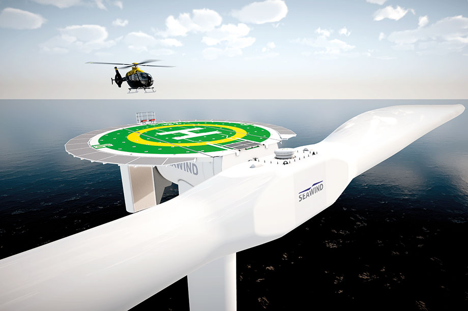
"The outer structure is internally reinforced by rafters like a ship’s hull, and structurally linked to a central circular-shape helicopter landing-deck that can accommodate large twin-engine helicopters.
"Uncomplicated helicopter-based service access is enabled with the turbine in stationary mode and the rotor locked in horizontal position."
DNV GL’s December 2019 report gave a positive judgment on the overall design of the self-containing nacelle with an integrated upper tower section and the bedplate-mounted non-integrated drivetrain layout, according to Caruso.
Design simplicity
This medium-speed geared drivetrain comprises a main shaft with two bearings and a large, fail-safe twin-disk brake system between.
The "floating" front bearing facing the rotor is an SKF Carb type, and the fixed double-row spherical roller bearing facing the gearbox absorbs both axial and radial loads.
The two bearing housings, gearbox and generator are directly mounted on rafters rather than on a (cast) bedplate plus separate welded generator frame as is more common.
From the start, Seawind’s product-development strategy focused on design simplicity and overall robustness to minimise the risk of turbine downtime offshore.
"For this reason, the planetary gearboxes for both the 6.2MW and the 12.2MW models have standard two stages and individual housings for each planetary stage, which will be procured from Chinese supplier DHHI. Unusually, they can be split both horizontally and vertically to enable easy access for inspections, on-site repairs and component exchange," says Caruso.
"Despite minimal deflections and deformations of the structurally stiff and strong nacelle, we decided on a gear coupling between the main shaft and gearbox to prevent rotor-induced non-torque loads entering the gearbox."
The simplicity philosophy is also reflected in the brushless induction generator with a full converter instead of a PMG.
The latter electric machines, in Caruso’s view, need more adequate magnet-temperature management and are more sensitive to longer-term operations and maintenance issues.
To protect the gearbox against peak-load related damages, such as a short-circuit of electrical equipment, a torque limiter is placed between the generator input shaft and the gearbox output shaft.
"The power converter, MV-transformer and switchgear are placed inside the integrated support structure base below water level," explains Caruso.
"This allows easy service access and passive seawater cooling, reduces vibration-related power electronics failure risk, and helps keep down nacelle mass."
The Seawind 6-126’s calculated head mass of 333 tonnes incudes the nacelle plus rotor, the upper tower section and the central part of the helideck.
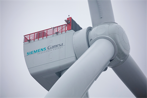
In comparison, the initial 6MW direct-drive Siemens SWT-6.0-154 had a head mass of about 360 tonnes, with a larger three-bladed rotor, but no helideck.
The Seawind 12-225 offers a calculated head mass of 647 tonnes (with the same elements as for the 6-126) and, at 225 metres, holds the record for the largest announced commercial rotor diameter. GE’s Haliade-X weighs in at 850 tonnes with a rotor diameter of 220 metres.

The floater's central column is surrounded by three tapering buoyancy elements
Back in 2017, two additional portfolio models were planned — Seawind 7 and 10.
"However, the offshore market developed at a faster pace. and our know-how base grew in parallel, so we decided to skip Seawind 7 and scale up Seawind 10 to become Seawind 12-225," says Caruso.
"By that time we had become fully confident that a leap to 12.2MW in a single step would be realistic and feasible, allowing us to skip Seawind 6 too. But our main investors insisted on reducing the overall project risk by first field-testing and validating the Seawind 6."
Market expectation
Jakubowski expects a limited market potential for the smaller model, largely concentrated on meeting clean power needs on remote islands and in hurricane-prone regions.
The main focus will be on the Seawind 12-225, initially aimed at high-wind projects in Europe and the US. Both sister models were developed for a design life of more than 25 years.
Inherently, to reach a given output, two-bladed turbines must either rotate one third faster compared with three-bladed equivalents, or alternatively deploy aerofoils that are one third wider.
The first option obviously increases tip speed and aerodynamic sound level, whereas the latter would make the two blades heavier and therefore more expensive.
The maximum rotor tip speed of the Seawind 12 is 139m/s, corresponding to 12.8rpm rated rotor speed.
This is exceptional compared with a state-of-the-art 90m/s range for offshore turbines such as GE’s Haliade-X and the MHI Vestas V164 and V174-9.5 MW series.
A common wind-industry view is that the optimal tip speed represents a compromise between aerodynamic performance and minimising the risk of leading-edge erosion damage.
![]() "A major benefit of the higher rotor-speed is a parallel reduction of input torque, which enables a lighter, cheaper drivetrain.
"A major benefit of the higher rotor-speed is a parallel reduction of input torque, which enables a lighter, cheaper drivetrain.
"And because aerodynamic noise is hardly an issue at sea, we could raise tip speed to 139m/s, thanks to technology from Connecticut-based surface-coating specialist Hontek," Carusa explains.
The US firm developed special anti-erosion coatings first applied successfully to resolve a costly issue with fast-wearing helicopter blades used by the US army in Afghanistan and Iraq (pictured), he says.
Because Hontek’s solution has proven itself in highly abrasive desert conditions, Seawind will use it for critical blade leading-edge surfaces. The company is considering applying the protective coating during the production process. It can be restored using drones or helicopters during operations.
"This is likely to be needed at five-year intervals and can be done without having to repair blades," says Caruso.
"The inherently higher centrifugal forces linked to our ultra-high tip speeds are compensated by more robust blades. The most critical factors during blade design are fatigue-related loads, but these are lower than in equivalent three-bladed-turbines.
"And the Seawind concept has eliminated centrifugal loads-sensitive pitch bearings by using a fixed blade mounting," he says.
Teeter hub
Two-bladed turbines are balanced aerodynamically but not dynamically. One measure to minimise high structural rotor-induced (bending) loads during operation, and especially yawing, is attaching the blades to a flexible structure with limited pivoting capability called a teeter hub.
However, in the past, premature teeter hinge wear was a notorious reason for failure in two-bladed turbines.
This is possibly why more recent two-bladed turbine designs — upwind and downwind — turned to rigid rotor mounting, including aerodyn’s super compact drive.

The teeter hub is a key factor of the two-blade concept, providing stability and reducing system fatigue
The Seawind 6-126 and 12-225 incorporate a patent-pending elastic teetering hinge, a solution whereby the blades are rigidly connected to a central square-shaped rotor hub at a fixed angle.
This hub is attached to the hinge-axis of a Seawind-patented T-shape main shaft via two elastic devices.
The system allows limited movement of the rotor disk around the hinge axis during normal operation, without hitting the bumpers even in extreme situations.
"One key finding was that the teetering angle [angular movement] of the Seawind 12-225 during normal operation is only about half the value of the Seawind 6-126, which practically means that the larger the rotor, the more stable the system becomes," Caruso says.
"This in turn helps to extend the teeter hinge’s design life by reducing fatigue cycles. The individually adjustable and exchangeable elastomer elements come with a self-lubricating journal bearing that is capable of effectively absorbing radial loads."
German vibration-solution specialist ESM is a main partner for the teeter elements. The overall benefits of the solution include optimal loads distribution within the teeter hinge elements for long operating life and high-level hinge torsional stiffness.
Active yaw-control
Seawind’s active yaw-control system offers two distinct control functions: the full rotor circle faces the prevailing wind directions until 12.5m/s rated speed; power output above this speed is controlled by adjusting the rotor angle relative to the wind direction as a function of wind speed.
The active hydraulic yaw system gradually turns the rotor out of the wind when the wind speed increases, and the initial full circle facing the wind becomes an ellipse with a reduced projected area.
This, along with an aerodynamic efficiency drop due to inclined less airflow at the blades, reduces wind capture and thus power output.
When wind speed falls below 12.5m/s, the inclined rotor plane returns to a full circle. The flapping rotor moments, a key factor with rigid rotors, are low due to the extra degree of freedom offered by the teetering hinge.
At wind speeds above the 25m/s cut-out speed, or another intervention cause, the hydraulic yaw system — fed by drivetrain-driven pumps — turns the rotor plane automatically 90 degrees away from the wind direction into safe-mode.
The blades are hereby kept in a horizontal position aligned with the wind’s prevailing direction and two disc brakes lock the rotor.
If the wind direction changes above a set value in parked condition, but depending on wind speed, the hydraulic yaw system fed by auxiliary electrical pumps automatically re-aligns the blades with the wind direction.
In the case of a grid failure, this manoeuvre is enabled by an auxiliary electric power source.
For typhoon-prone sites, the turbine will be fitted with two lidars to detecting approaching winds at a 2km distance over 360 degrees for changes in wind speed and direction.
The blade tip facing the wind is kept aligned by the controller, which receives data from the lidars in real time.
When a wind gust hits the blade, the energy is absorbed by the flexible teeter hinge, flexible yaw lock and main shaft locking together.
Hurricane simulations
"Numerical simulations by Seawind using Bladed software and the Polytechnic University of Milan deploying its advanced in-house Cp-Lambda software tool indicate that Seawind turbines can withstand category 5 hurricanes [90m/s peak] without suffering extreme-load-related damages," says Caruso.
"The loads acting on blades and drivetrain are close to those during normal operation at cutout, because our flexible setup behaves in line with the forces of nature rather than fighting them. An additional wind tunnel test is planned for extra validation."
The (future) supply chain set-up follows the "Airbus model". This involves producing the concrete sub structures (see "Integrated support structure" section) in a dry dock, which also serves as the final assembly line for mounting the turbine and all sub-systems, similar to the way the European plane maker works in Toulouse, France.
Components and sub-systems will be sourced from Europe and beyond.
"Our goal with the Seawind 6-126 demonstrator planned at the European Marine Energy Centre in Scotland is to produce green hydrogen with next-generation electrolyser technology from a Canadian partner," says Jakubowski.
The 12.2-225 is also planned for UK waters, but the location will be disclosed at a later stage," Caruso concludes.
Integrated support structure for floater and fixed bottom
Seawind considers turbine head, tower, and substructure one integrated system. This strategy applies to the in-house developed bottom-fixed tetrapod support structure for water depths up to 50 metres, and to a second floating semi-sub solution alike.
Both full-concrete support structures allow vertical turbine mounting at "protected" shipyards or quay sites, followed by tugboat assisted floating to wind farm sites for completion in a "self-installing" offshore process.
The 12.2MW floater is composed of three tapering 38-metre high buoyancy elements and a central column for tower mounting.
A full system will be moored with three anchor-mooring stations, and each will have a double cable/chain linkage for providing operational redundancy.
"Seawind’s active-yaw turbine control effectively prevents wind and wave movements impacting the rotor due to the teeter hub that acts like a cardan joint," says Silvestro Caruso, Seawind’s chief technology officer and co-founder.
"The response of the rotor thrust to system oscillations caused by waves ‘brakes’ rotor-disk movements. There’s no negative damping. In addition, the elasticity of the system — present in the Seawind 6 and to a higher degree in the Seawind 12 — limits the oscillations induced by the highest waves, which may occur in parked condition in typhoon-prone sites."
Early days — Seawind history
 Seawind 6 builds on company co-founder Silvestro Caruso’s experiences with the Gamma 60, a two-bladed 1.5MW variable-speed, active-yaw-controlled research turbine of the late 1980s.
A prototype was installed in 1991 in Sardinia, Italy.
The turbine suffered fire damage during a 1995 storm caused by human error, and was put back into operation until 1997, when the R&D programme was discontinued.
Active-yaw control as a principle will work for both upwind and downwind, but Gamma 60 testing showed that an upwind rotor is aerodynamically more stable.
An upwind rotor is also not affected by tower shadowing impact when individual blades are passing the tower, which greatly reduces fatigue loading.
Seawind technology heritage dates back to US aerodynamics and helicopter pioneer Glidden Doman, who studied and explored structural dynamics of large two-bladed wind turbines in the 1970s at NASA.
.png)

.png)