The year 2017 showcased a number of developments for the?German engineering consultancy.
One was the successful bench-testing of a 3MW SCD upwind model at the RWTH Aachen technical university before shipping it to Japan.
There it will be mounted on an Ideol floating platform as part of demonstration project for Japan’s new Energy and Industrial Technology Development Organisation.
Another was the introduction of the 15MW SCDnezzy2 concept at the WindEurope offshore event in London during the summer.
The radical twin-rotor design was judged winner in “uåX˜äŠÊ˜·³Ç’s 2017 product of the year innovations category.
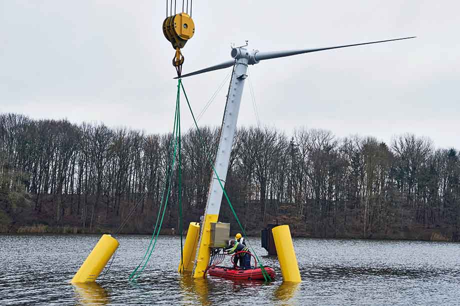
The yellow-coated SCDnezzy model entered the water for the first time on the day before its presentation at the Nobiskrug Werft shipyard in Rendsburg, northern Germany.
The envisaged highlights of this technical exercise would be to watch its self-yawing capabilities together with the first operational spin, but, unfortunately, a lack of wind prevented this.
Experiencing the operational behaviour therefore had to wait for the start of a three-month testing period in Japan, scheduled to start in the third week of 2018.
This tight schedule?demanded the complete dismantling of the installation immediately after the event in Germany, for air transport to Japan.
"The test model undergoes a three-month testing and validation programme, during which it will be exposed to real?marine environment conditions," says Jan-Christoph Hinrichs, the firm’s head of research.
"However, because this is a scaled turbine, we chose a more sheltered environment on Japan’s east coast in Kure, near Hiroshima.
"This site is characterised by mean wind speeds of around 7m/s and a one-year wave height of one metre, which are modest conditions compared to the far more demanding open sea environment around Japan."
Test objectives
The main areas of investigation during the tests in Japan are:
-
gaining insight into floating turbine assembly;
-
the combined installation and commissioning processes;
-
efficient pre-installation methods;
-
optimising the number of mooring lines.
The results from the various tests and measuring campaigns will be used for detailing the full-scale 6MW SCDnezzy prototype, which is planned to start operating at a Japanese site in 2020.
"Semi-submersible floating structures like SCDnezzy offer the highest flexibility compared with alternative floating solutions, but we still need to build experience with various sea states and operating conditions," says Hinrichs.
"One planned test trial, for instance, is studying its operating behaviours in 03.m/s sea currents at operational draft, which corresponds to 1m/s for a full-scale SCDnezzy turbine. Another planned test involves studying the installation alignment during a wide range?of combined wind and wave loads."
Instrumentation
The introduction of the test model was organised inside a main hall with the fully instrumented installation featuring a scaled rotor on display, resting on three heavy supports. Despite the downscaling, the structure’s dimensions are still substantial.
The display offered a clear view of some specific SCDnezzy characteristics, such as the Y-shaped semi-submersible structure composed of one long leg, two shorter legs and three inward-facing buoyancy columns.
The upper surfaces of these columns serve as linkage points for the guy wires that support and stabilise the inclined tower and two-blade downwind turbine atop.
"The straight, hollow eclipse-shape intermediate sections of the floater elements are made of steel-reinforced concrete and come in a single piece," explains Hinrichs.
"One side of each individual section is bolted airtight to the central floater section with a tower mounting flange. The other side is attached to an outer section with buoyancy column.
"The enclosure created forms a main part of the water-ballasting system operated by air pressure. The ballast system is just for installation purposes; the model has no active ballast system during turbine operation."
Ballast water will be released before a fully commissioned SCDnezzy is towed to its offshore destination. During this operation, a large proportion of the floater body is raised above the water surface. This is primarily to reduce water resistance (drag) during towing.
Each fabricated welded steel outer section comprises an eclipse-shape horizontal part, welded to a round semi-vertical tube to accommodate a matching inward-facing aluminium buoyancy column. The central floater part with tower-mounting flange is also made from fabricated welded steel.
Several engineering solutions used for the test model are specific to the test model, and others design-specific for SCDnezzy. One typical example of a dedicated test model solution are the single-piece intermediate floater sections. These will be segmented for the full-scale 6MW turbine.
Catenary mooring
Design specific for SCDnezzy — and the test model — is a dual-mode single-point catenary mooring system incorporated in the long floater arm. This feature allows the full floater to rotate, and it incorporates a slip-ring unit for transmitting turbine power to a marine AC or DC cable.
The main benefit is that it reduces the system’s complexity by eliminating the need for an individual turbine-yaw system. The inlet droplet-shaped guyed tower solution was first seen in 2014 with the 8MW SCDnezzy 8.0.
"Our initial SCDnezzy 8.0 concept featured three individual buoyancy elements linked by cables or chains to the submerged floater out parts, and the guyed tower support wires were attached to the same elements," says Hinrichs. "Since the product introduction we have continued to consult leading experts regarding different areas where improvements could be made."
One commonly expressed concern was over the lifetime of wires when operating submerged for prolonged periods. A rethink resulted in a major design change to semi-vertical buoyancy columns integrated with the floater’s main elements, and a different elevated guy wire attachment method.
In London last year, the company also displayed a 1:36 scale model of the SCDnezzy2 15MW, which already featured these latest design modifications. This test unit underwent successful wave basin testing in Cork, Ireland in 2017.
Among the simulations carried out were scaled wave heights of up to 30 metres, not uncommon in the Atlantic. A key focus for SCDnezzy technology is minimising floater movements to a maximum inclination of 3.8 degrees and maximum accelerations to 0.4G. These simulation outcomes were validated in Cork.
Rotor size increments
The test model’s rotor represents one-tenth of a full-size SCDnezzy 6.0 turbine rotor, envisaged for the next-stage Japanese demonstration project. Rather confusing is that?the initial 6MW SCD prototype installed in China by former Aerodyn licensee Ming Yang features a 140-metre rotor?diameter.
"We intend to increase the rotor size to 150 metres, which matches our latest 7.5MW SCDnezzy upgrade from 6MW, and which was introduced last year for the 15MW twin-rotor SCDnezzy2," says Hinrich.
"The demonstration project permit is only valid for a 6MW rated capacity, so we decided not to fit the 150-metre rotor for this project. But for other projects this rotor size will be available to cut LCOE," he says.
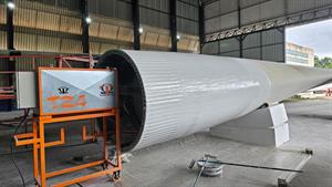
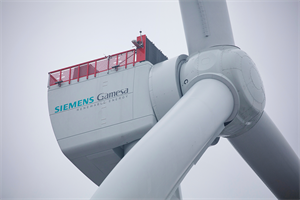
The engineering team further retained the same rated tip speed of the full-scale blades for the scaled-down model. The mass of an original blade measuring nearly 75 metres is about 25 tonnes, and the down-scaling required a reduction to 250kg to match the scaled blade of nearly 15 metres.
Aerodyn’s in-house experts switched from the original glass-fibre reinforced expoxy (GFRE) laminated blade to 100%?carbon fibre reinforced expoxy (CFRE), pictured below.

"This design process turned out well. The scaled blade is stiffer than expected and, fortunately, does not suffer from any critical excitation frequencies in the turbine operating range," says Hinrichs.
"However, during the development process, we also realised that designing a kilowatt-size turbine requires building specific new expertise, despite our more than 30 years of experience with dedicated wind-turbine and main components design.
"We also underestimated the engineering effort required for this 1:10 scale turbine. We initially expected around two to three months’ work, but it turned out to take much longer."
A positive outcome, according to Hinrichs, is that the extra design engineering effort could at least be partly compensated for by a smooth shipyard manufacturing process, reinforced by a flexible approach of all project partners.
Lessons learned
Elaborating further on the combined engineering challenge, Hinrichs adds that developing a scaled turbine does not simply mean scaling down from an existing turbine size. Instead, almost everything had to be calculated anew.
Some components, such as power electronics, require a specific size and corresponding mass to fulfil their specific functions "The cumulative mass of the SCDnezzy 6.0 power electronics is around 270kg, and we could hardly reduce this figure for the scaled test model," says Hinrichs.
"A big lesson learned is that properly scaling down a turbine and its main components from a given size is more complex than we all expected, and definitely something that should not be underestimated."

.png)
HR.jpeg)
.png)