Any turbine-control system algorithm is based on a set of mathematical equations, increasingly fine-tuned for specific turbine models and their dedicated applications.
The main benefits include controlling turbine loads as a function of generator nominal torque and speed from pre-set cut-in (engaging) to cut-out operating conditions and wind speeds.
Turbine control integrates software-based functionalities with main hardware components, especially pitch and yaw systems, generator and converter.
Early versions
The initial pitch-controlled variable-speed turbines were fitted with rotor diameters in the 30-80-metre range, and collective pitching was state of the art. The control algorithms used were still rudimentary, with output control as the main function.
As rotor sizes grew, the matching longer blades experienced increased variation in blade loading due to height-related wind-speed differences across the rotor plane.
This led to the development of cyclic or individual pitch control (IPC) technology, which first became on commercial wind turbines. in 2003.
With these first-generation "classic" IPC systems, individual blade-pitch angles are readjusted in a predetermined angular cycle relative to rotor position per rotor revolution.
Classic IPC faces increasing competition from more advanced, load-based IPC technology. Individual blade-root loads are now measured in real time using sensors, enabling each blade’s pitch angle to be optimised with the aim to minimise rotor and turbine loading.
Advanced insights into real-time blade loading offer multiple benefits, including a reduction in extreme loads, resulting in lighter, more cost-effective overall turbine design and, ultimately, reduced levelised cost of energy (LCOE).
Some suppliers of (low-wind) onshore and large-scale offshore turbines fitted with the latest loads-based IPC technology switched from four-point ball-type pitch bearings to a three-roller type to meet extended pitch-bearing lifetime requirements.
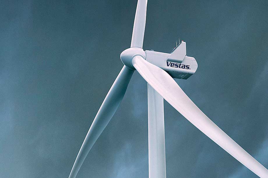
Chris Spruce, senior product engineer and control-systems expert at MHI Vestas, first worked on load-based IPC early this century when developing the NEG Micon (now Vestas) NM92/2750 and the 4.2MW NM110/4200.
"Vestas first introduced load-based IPC in the V90-3.0MW, deployed both onshore and offshore. Further developments have taken place since, and the technology is already used in thousands of turbines," he says.
"For the [MHI Vestas] V164 series, we apply standard tried-and-tested Vestas algorithms, with their parameters tuned to give the best results for the specific turbine type and operating environment."
Wave excitation
Load control of large-scale offshore turbines has some different challenges compared with onshore wind, Spruce points out.
The support structure (tower plus foundation) experiences wave excitation, the first rotational excitation frequency (1P) from wind loads on rotating blades, and a second frequency caused by the (three) blades passing the tower (3P). The first natural frequency of offshore wind support structures lies between the wave and 3P natural frequencies.
"With increasing turbine size, the support structure, 1P and 3P natural frequencies drop, leading to increased wave loading," Spruce explains.
"And a bigger rotor necessitates increasing hub height to retain the same ‘free distance’ of a rotor-blade tip in bottom position to sea level, which impacts support-structure length and dynamics.
"Before the current turbines in the 7-8 MW range were developed, there were concerns about the effects of reducing natural frequencies and turbine loading, but the challenges have not proven to be severe, and have been overcome."
Offshore foundations cost significantly more than their onshore counterparts, therefore reducing mechanical loading on the support structure through advanced control is proportionally more beneficial, Spruce argues.
Another challenge is finding optimal solutions for offshore turbines typically operating as part of large projects, he adds.
"With a south-west prevailing wind direction, for example, turbines at the north-east corner of a wind farm experience higher fatigue loads resulting from wake effects across the [project]. Our control algorithms are flexible enough to give high performance both in the free, undisturbed wind and when operating in wake-induced turbulence."
Pro-active
In general, control-system solutions are arrived at via both reactive and pro-active routes. Reactive steps might prove necessary when a new turbine type, installed for the first time, experiences a major issue requiring an immediate solution.
"For any new product platform, our experts decide which algorithms to use. The key is to fine-tune all available parameters," Spruce says.
"This could involve moving loads from a mechanically highly stressed area to one with design reserves left. During such integral design processes, engineers pro-actively come up with new ideas for changes in control strategy, such as offering a reduction in loads and/or higher output.
"In the end, it is the combination of challenges driving a design, and both software and hardware solutions must be proven and reliable," he says.
Onshore progress
At 150 metres, the latest Vestas V150-4.2MW for low-wind IEC IIIB/S applications features one of the world’s two largest onshore rotor size.
The product development of this model and of the V136 and V117 sister 4.2MW models for IEC IIB/IIA/S and IEC IB/S classes respectively presented a formidable overall design challenge.
"This new turbine series builds mechanically and electrically on the V136-3.45MW and earlier 3MW platform models. A main product development focus was to do whatever necessary to further drive down LCOE, which was not simply a matter of adding blade length and increasing turbine rating," said Jan Hagen, Vestas’ vice president for product strategy, when the turbine was launched this summer.
Vestas engineers further succeeded in keeping nacelle dimensions virtually unchanged compared with the V112-3.0MW, despite the rotor-swept area increasing by almost 80% and input torque by more than 50%.
According to Hagen, other figures indicate the rotor-swept area has increased by 21.7% compared to the V136-3.45MW, which is expected to boost annual energy production by more than 20% at representative sites. Head mass is calculated to increase by less than 10%.
Evolutionary
The V150 control system is a latest evolutionary integrated software and hardware-based development backed by almost a decade of research and development, as well as experience in the field with a large installed fleet encompassing thousands of turbines of this platform.
Equally important is the continuous support and feedback of the Vestas Performance and Diagnostics Centre, including the technology-validation campaigns it is engaged in.
The accumulated track-record know-how has, according to Hagen, led to a deep understanding of all critical aspects in turbine design, such as highly complex aero-elastic behaviour and stability.
"One major challenge was solving these critical areas, including mitigating loads whenever possible, but without having to add much material to main components like the new in-house 73.7-metre blades, and the mechanical structure. We managed to complete this process fast, and with a good degree of confidence based on our field experience and data," he says.
"What further proved a great overall benefit is that Vestas, for almost two decades, has had in-house manufacturing of critical control-system hardware elements, as well as modular converters for all its platforms and will continue to do so for the 4.2MW series."
The V150-4.2MW comes with hub heights up to 166 metres, and this configuration, combined with forested and other high-turbulence sites, will experience high wind-shear loading and substantial variety in rotor wind speeds.
Under such conditions, the rotor could be exposed to IEC III wind speeds with the blade in bottom position, IEC II when semi-horizontal, and IEC I when reaching top position.
Frequent pitching
The 4.2MW series is therefore equipped with load-based IPC, as demanding conditions often involve frequent pitch activity, Hagen says.
"Vestas has applied hydraulic pitch systems for decades, and the combination of higher capacity in that system and advanced control algorithms offers a high degree of sophistication of the overall system.
"It allows a choice between extra loading of the nacelle systems or the pitch system, depending upon whether it is incorporated in the V117-4.2MW or V150-4.2 MW.
"These options all add to offering our global clients the most optimal LCOE-based solutions," Hagen adds.
Early days — "Classic" individual pitch control
GE introduced "classic" individual pitch control (IPC) for a new 2.5MW 2.5xl model in 2008. The main claimed benefits were substantial fatigue load reductions: 10-15% for hub and blade flange, 6-10% for the tower base (fore/aft), and 15-20% for the tower base (side/side).
The "penalty" was a 50-100% increase in pitch actions, with risks of accelerated pitch-bearing wear, premature failures and higher turbine downtime.
GE presented its IPC solution as offering two optimising options, a larger rotor or a less expensive turbine. The US manufacturer chose to increase the rotor to 100 metres from an initial 88 metres, without having to lower IEC class or strengthen the hub, drivetrain and tower.
.png)

.png)