Nearly all modern wind turbines operate with variable speed and turnable rotor blades (pitch-control). Initially, rotor diameters of 30-80 metres were common and collective pitching was considered state of the art.
However, as rotor sizes continued to grow, the longer blades experienced increased variation in blade loading due to height-related wind speed differences across the rotor plane. This unwelcome phenomenon initiated the development of cyclic or individual pitch control (IPC) technology over the past decade (see cyclic pitch control, below).
With these first-generation "classic" IPC systems, individual blade pitch angles are changed in a predetermined angular-adjustment cycle dependent on the relative rotor position.
Classic IPC faces increasing competition from more advanced load-based IPC technology. This is, in essence, a control strategy whereby individual blade root loads are measured in real time with sensors and then "translated" into matching individually optimised blade-pitch angles to minimise rotor and turbine loading.
Experts expect a great deal from these new IPC systems, because insight into real-time blade loading offers multiple competitive benefits, including a reduction in extreme loads, resulting in lighter, more cost-efficient overall turbine structural design.
An extended service life requirement of 25 years has become common for better return on investment, and, ultimately, reduced levelised cost of energy (LCOE).
German slewing bearing specialist IMO currently engineers T-Solid 4IPC pitch bearings for low-wind onshore turbines with rotor diameters in excess of 130 metres and incorporating load-based IPC. Parallel efforts for 6MW offshore turbines — including two-bladed configurations — with rotor sizes over 140 metres are in progress.
Ring separation
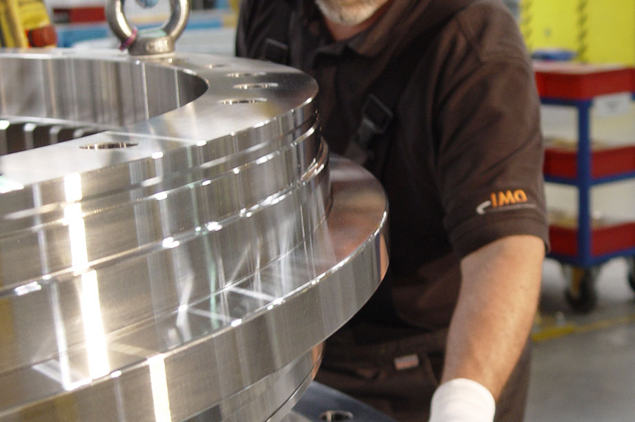
 IMO's initial ball-type T-Solid pitch bearing is specifically focused on low-wind onshore and large-scale offshore, with the design's main emphasis on minimising ring separation.
This infamous phenomenon is known from widely used four-point contact ball-type pitch bearings, causing grease leakages, while ring deformation stress negatively impacts bearing fatigue life.
This T-Solid design principle is an evolution of double-axial ball bearings known from decades of application in large cranes, for example, but with separate radial raceway.
According to IMO chief engineer Hubertus Frank, these heavy-duty applications require smooth operation while facing high tilting moments and heavy deformation of the bearing mounting support structures. This compares well to the load types and mechanical design limitations faced by onshore and offshore turbines with very large rotors.
"The most favourable functional difference between ball-type T-Solid and conventional four-point bearings is that the dominant moment load is now fully carried by a pair of axial forces without causing rings separation," says Frank (see scaling challenge section, below).
The new roller-type T-Solid 4IPC bearing design focuses on comparable applications, but with an additional emphasis on enhancing operating life when combined with IPC and extended 25-year design life. The minimising of ring separation and ring stresses remained an overall focus. T-Solid 4IPC incorporates two axial and one radial row of cylindrical rollers.
Proven solution
Roller elements are widely used, including in IMO's large-diameter single main bearings, and have been a proven solution for decades. However, using roller elements for a blade bearing application is a major engineering challenge, says Frank. "One aspect was in dealing with the substantial deformations resulting from huge aerodynamic forces acting on the blades of large rotors.
"The balls incorporated in four-point and ball-type T-Solid pitch bearings can freely move along their curvature perpendicular to their ball path during operating conditions with no pitching activity. Such free movement of rollers in T-Solid 4IPC is constrained as they are positioned in-between two flat raceway paths."
Without adequate counter-measures, this could introduce peak-load stresses at the roller ends, resulting in rolling-fatigue-related flaking damage, especially when the bearing's structural design has insufficient stiffness.
Flaking is a phenomenon that occurs when small pieces of bearing material break free from the smooth surfaces of the raceway or rolling elements. It creates a rough coarse texture at the damaged sections and causes a rapid end to bearings' useful life.
In addition to the overall challenge, blade bearings for high-pitch frequency in full IPC turbines cannot easily be tested via highly accelerated life testing (HALT), therefore different testing methods will be required, says Frank. One of these planned testing set-ups is aimed at better understanding the complex roller movement path inside T-Solid 4IPC bearings.
Longitudinal
One main study topic is linked to the fact that rollers not just roll but also experience longitudinal displacement due to general bearing deformation.
"This is the worst condition for determining bearing-design life expectancy, since the rollers - besides rolling all the time - scratch lengthwise perpendicular to their raceway path and thereby face an increased risk of losing the necessary grease lubricant film," Frank says.
On expected LCOE benefits T-Solid 4IPC application could offer, IMO managing director Werner Schroppel provides several numbers derived from typical low-wind onshore turbine specifications. For the tower he assumes 28-30% of turbine Capex, whereby high-rise towers often used at low-wind sites position these at upper end of the cost scale.
Pitch systems, including bearings, pitch drives and control, and fail-safe back-up systems by comparison account for about 4%. "It is realistic to assume that blade bearings account for 50% of pitch system cost, or 2% of Capex," Schroppel adds.
"Even if the T-Solid 4IPC blade bearing cost would come at a 50% premium, it would only require a 3-4% tower cost and additional foundation cost reductions to break even."
This is a conservative estimate since switching to T-Solid 4IPC will reduce turbine structural loads and cost significantly. Schroppel expects T-Solid 4IPC to gain market share from 2018. "We can move fast because T-Solid 4IPC builds on experiences and comprehensive tests with ball-type T-Solid. We 'only' had to replace balls with rollers to achieve a ten-fold increased bearing life requirement for IPC," he says.
Cyclic pitch control — GE pioneers technology allowing larger rotor
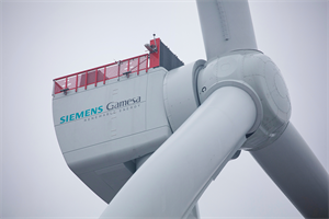
During a technical conference in 2008, GE gave a presentation on "controls for load reduction", introduced as (cyclic) individual pitch control in its new 2.5MW 2.5xl flagship turbine.
The technology's main benefit was a substantial reduction of fatigue loads: 10-15% for the hub and blade flange; 6-10% for the tower base (fore/aft); and 15-20% for the tower base (side/side). However, the penalty paid for these substantial overall load reductions was a 50-100% increase in pitch actions.
Incorporating individual pitch technology itself was further presented as choosing between two optimising options: a larger rotor or a less expensive turbine. GE went for a larger 100-metre rotor instead of retaining the initial 88-metre size. The single main benefit noted was that a larger rotor generates more power without having to reduce IEC class and, in parallel, strengthens the hub, drivetrain and tower.
The GE expert concluded that the initial pitch rate of eight to ten degrees per second could be retained with the new pitch technology.
During the initial years following IPC introduction at a small-scale, experts were divided about the real benefits. Critics kept warning that a marked increase in pitch actions would inevitably lead to much-accelerated pitch bearing wear, premature failures and, ultimately, higher turbine downtime.
Pitch bearing scaling challenges dealing with aerodynamic loads
During turbine operation, pitch bearings are exposed to moment loads, aerodynamic thrust forces and gravity load-direction changes twice per rotor revolution. For the latest large rotors, aerodynamic moment loads have become the design driver.
"Conventional four-point contact ball-type blade bearings consist of two axially interspaced rows of balls incorporated in an inner and outer bearing race," says IMO chief engineer Hubertus Frank. "Moment loads supported by the bearing internal raceway system introduce axial and additional radial forces, and the latter cause rings deformation and separation," he explains.

Reduced life… Conventional four-point contact ball bearings face hazardous raceway edge loadings
Standard lifetime calculations, following a traditional methodology, consider the blade root and rotor hub as infinitely rigid. Only the raceway system shows deformation under load. As a consequence, finite-element analysis is mandatory to determine the real loads and bearing life expectancy."
Such calculation methods are inadequate for current 3-4MW low-wind onshore and 6-8MW offshore turbines because the two interlinked negative effects reinforce each other, according to Frank, "The specific raceway loading worsens when bending moment-induced loads increase while the ratio between the rotor diameter and the pitch-bearing size cannot be improved through blade root diameter increments for technical feasibility and Capex reasons."
Structural stiffening
Furthermore, the stiffness of hub and blade root is generally insufficient to fully match these moment load increases. OEMs try to counteract the resulting blade root and hub dynamic deformations by adding structural stiffening plates and extra reinforcements between blade foot-to-bearing and hub-to-bearing.
Cyclic deformation of bearings raceway geometry is shown by gap width variations between the inner and outer race.
Says Frank: "The balls as a result no longer roll along an ideal spherical pathway but at a raceway that opens elliptically towards the edge. The combined negative impacts pose a major threat to the operating life expectance of large-diameter classic four-point bearings, unless massive stiffening is incorporated.
.png)


.png)