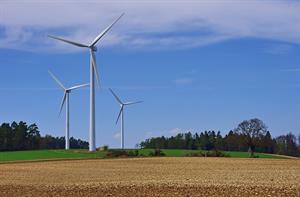
Around 80% of all wind turbines installed in 2014 followed the same pattern — a high-speed geared drivetrain, an upwind rotor and three rotor blades. Direct-drive turbines have their devotees, however, with Enercon and Goldwind the leading suppliers. And while the role of lowand medium-speed drivetrains remains small, it might grow over the next few years, especially in the new generation of 3.5MW-plus onshore machines and large offshore turbines.
One key player in the medium-speed segment is German component manufacturer Winergy, which claims that nearly one in three wind turbines installed worldwide is equipped with its gearboxes and couplings. Winergy's HybridDrive is a novel semi-integrated solution, comprising a gearbox incorporating two planetary gear stages and a flanged permanent magnet or classic synchronous generator. The main benefits of HybridDrive and comparable medium-speed solutions are compactness and reliability: the flanged gearbox-generator connections effectively eliminate misalignment-related issues, and the system is free of the more trouble-prone high-speed gear stage.
Optimising cost of energy (CoE) performance is a fundamental objective of the wind industry, best expressed as lifecycle-based capital expenditure (Capex) plus operating expenditure (Opex), divided by lifecycle cumulative yields. Lower component costs, easier transport logistics, and optimised installation methods all have a positive impact on Capex. This applies too for project insurance premiums, which are closely linked to the reputation of the product and supplier, together with a calculation of real risks and risk perception. Project Opex depends on many different factors, ranging from the quality and reliability of the components and systems used to the service of the supplier.
Family connections
Original equipment manufacturers and their component suppliers are increasingly working on turbine platform families - models that can be adapted for different wind classes. Technical specifications are especially aimed at optimising the ratio between the power rating and the rotor-swept area, which generally requires the fitment of larger rotors when a turbine is adapted from a high-wind IEC class I rating to a medium-wind class II or low-wind class III specification. Sometimes the power rating is adapted in parallel with the longer blades.
For example, the Nordex Delta series consists of a 3.3MW turbine with a 100-metre rotor diameter for IEC class I (N100/3300), a 3MW model with a 117-metre rotor for IEC class II (N117/3000), and another 3MW machine but with a 131-metre rotor for IEC class III (N131-3000). For onshore turbines, the fitment of a larger rotor with an unchanged power rating usually requires a reduction in rotor-rated speed to curb aerodynamic noise.
The consequence of this, however, is that gearbox input torque increases, which in turn requires upgraded gearbox components, such as thicker shafts, stronger bearings, wider gears and different gear ratios. Some suppliers might opt for a reduction of generator power rating when fitting a larger rotor to keep the rated gearbox input torque constant.
This enables "standardised" gearbox design for the lowand medium-speed (planetary) gear stages, with only changes to the final stage gear ratio for matching generator speed.
A comparable strategy can be employed for direct-drive turbines. In 2011, when Siemens introduced the 2.3MW SWT-2.3-113 model, based on the 3MW SWT-3.0-101, former CTO Henrik Stiesdal said: "Due to the larger rotor diameter, we reduced rotor speed from 16rpm to 13RPM, but generator torque level remains unchanged. Besides a substantially higher energy production at low and medium-speed wind sites, a second main benefit is that we can use the same generator for both models."
Dedicated designs
In the pioneering days of the wind industry, suppliers commonly applied (semi-) standard gearboxes and generators in turbines with comparable power ratings and rotor diameters. The same could be said for the blades, and some smaller turbine makers today still pursue an external sourcing strategy based on using semi-standard third-party blades.
But now the preference for dedicated gearbox designs has taken precedence, even when main component specifications closely match those of competing turbines. However, for high-speed generators, such as 1.5-3MW doubly fed induction generators (DFIG), turbine suppliers can relatively easily outsource semi-standard components. Direct-drive generators are typically dedicated main components, often developed and manufactured in-house.
Standardising is possible to a certain degree for mechanical components such as yaw motors, although the number of motor units will vary according to the main variables of rotor diameter and power rating. Power electronic parts, like converters, can be split into standard modules, thereby also offering redundancy capability by allowing continued operation at reduced capacity in case of module failure. Another example of standardisation is the reapplication of a given rotor assembly (hub and blades) to a new turbine model. This again enables producing larger series of similar components and systems while minimising development costs and risk, and reducing time to market.
For main bearings there is a wide choice of alternative options, ranging from large-diameter single bearings, with or without main shaft, to more traditional solutions comprising one or two smaller-size bearings plus main shaft. Large-diameter single-rotor bearings are dedicated components offering a compact nacelle design, which has made it a popular option for the industry. Simultaneously, substantial care is required in creating a strong and structurally stiff bearing support structure, which adds to main carrier mass and cost.
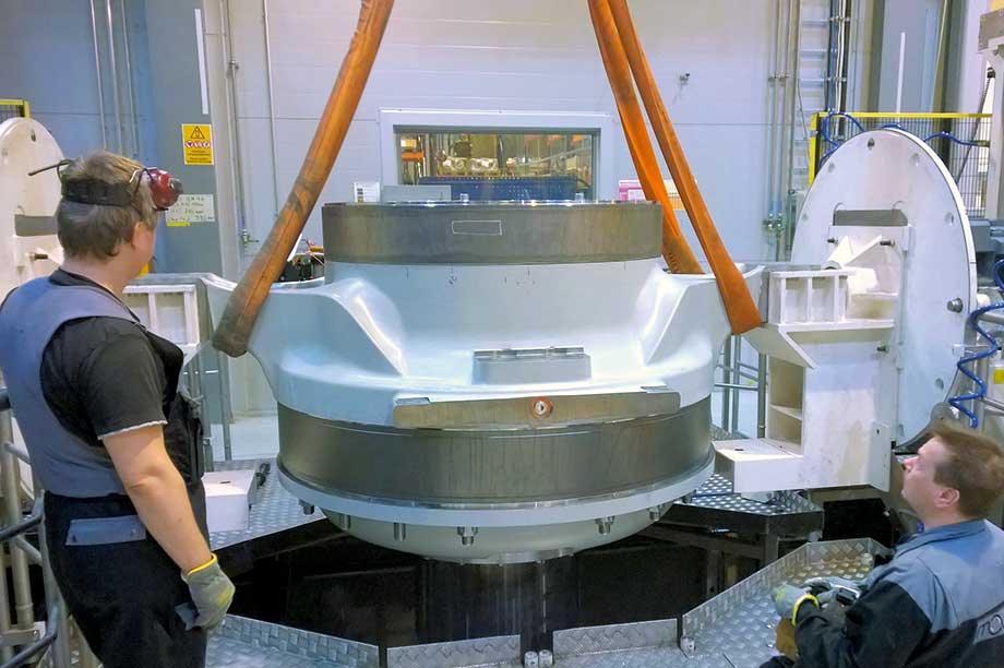
Until recently, big main components, including gearboxes and large generators, were transported from the equipment supplier to the turbine assembly facilities for final fitting. But the growth in size and mass of turbines has complicated the logistics and pushed up transport costs, leading to on-site delivery of separate building blocks such as drive components and "empty" nacelles for final assembly.
Space constraints
Traditional single-piece blade manufacture is labour-intensive and represents growing manufacturing, transport and installation challenges as blades get bigger. Some industry observers suggest the maximum viable transportable single-piece blade length for onshore turbines could be in the 65-metre range.
For its 3MW E-115 and the new 4.2MW E-126 EP4 turbines, Enercon developed a new generation of fully composite segmented blades, with the inner and outer sections joined mechanically. Enercon's innovative in-house manufacturing technology for the inner segments involves machine-wrapping pre-soaked fibreglass plastic around a positive cylindrical core, which in ready form constitutes the load-bearing structure. An aerodynamic trailing edge "add-on", which includes the company's characteristic integrated spoiler, is bonded with this "blank" creating the final aerofoil structure and shape.
Although the manufacturing costs of segmented blades is likely to be higher than single-piece units, this is compensated for by cost savings during transport and installation, especially at space-constrained forested and other complex sites. A parallel wind-industry trend for such demanding sites is the introduction of cranes that can be erected close to turbine foundations for additional crane ground support.
For its 3MW family of onshore turbines - with rotor diameters of 116, 125 and 132 metres - Spanish turbine supplier Acciona applies a modular blade design comprising a shared structural blade up to 48 metres with the same aerodynamic shape, but adds extendable tip sections. The two parts are joined by composite bonding into a single assembly. The latest 64.7-metre blade for the AW132 sets a new 132-metre rotor diameter record in the 3MW onshore class.
German blade developer and supplier Euros also used a modular segmented mould - subdivided in root, middle and tip segments - for the 81.6-metre blade fitted to the 7MW Mitsubishi SeaAngel offshore turbine prototype, providing a rotor diameter of 167 metres. This innovative approach enables customised blade lengths, root-bolt diameters, and additional on-demand features.
UK-based Blade Dynamics develops lightweight modular blades comprising a segmented root section, patented root inserts, a carbon-epoxy modular inner spar, and multiple modular aerodynamic cladding sections. This technology enables factory pre-assembly in relatively modest segment lengths and on-site final assembly with uncomplicated assembly jigs.
Tower options
Concrete-steel hybrid towers of different designs are the wind industry's preferred choice for installations requiring hub heights in excess of 100 metres. They can be easily adapted to match different turbine ratings and hub heights. Alternatives include towers in wood or bolted steel — either composed of tubular steel segments (Siemens and Lagerwey) or, for example, GE's lattice-type spaceframe tower. Alternative solutions for sites without road transport or diameter constraints include especially wide-base tubular steel towers. The latest industry trend is towards hub heights in the 160-metre range for onshore turbines fitted with 130-metre-plus rotor diameters.
LIFETIME EXTENSION - AND ITS IMPACT ON LIFECYCLE ASSESSMENT
Wind turbines recover their cumulative energy inputs through energy production usually over between four and nine months, depending on location. Average wind speed at hub height is the key variable for onshore and offshore. Water depth (foundations) and distance to shore (length of cables) are additional variables for offshore turbines.
Inputs encompass all energy contributions - from extracting raw materials to component and complete turbine manufacture, transport/logistics, turbine installation, the operating phase, to final decommission, demolishing and recycling.
Now assume a 20-year (240 months) design life and an energy payback period of six months. This results in an environmental performance or harvest factor of 40 (240/6). Again assume the same turbine is certified for 25 years, which is now becoming common for offshore. If turbine availability (function of reliability and service performance) remains unchanged, the harvest factor increases by 25% to 50 (300/6).
For many years turbine up-scaling was a continuous factor, and this timespan seemed realistic because timely repowering of wind sites with new, bigger and better-performing machines would offer an attractive business model. Today, the onshore volume market is substantially characterised by mature utility-type turbines in the 1.6-3.5MW range, offering matching specifications to suit the demands of most sites.
Extending lifespans
However, in a number of cases the upgrading of existing sites with larger installations is not possible because of factors such as height restrictions or grid capacity limitations. In these cases owners and operators try to extend the lifetime of their existing turbines by fitting refurbished components, such as gearboxes, generators and blades.
Some suppliers — Gamesa provides a good example — already actively focus on the market opportunities for turbine lifetime extension, offering reconditioned components that have been restored to original specification, or even improved by eliminating weak spots in the original design.
Enhancing turbine lifetime yields and extending turbine operating life make a positive contribution towards minimising a turbine's lifecycle footprint. Optimising both the cost-of-energy and lifecycle-assessment footprint have become key drivers for the wind industry. Together they play an increasing role in determining future technology choice and direction.
.png)

.png)