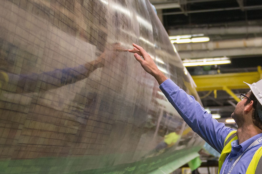
A warehouse on the Michoud Assembly Facility in New Orleans, Louisiana, once part of US space agency Nasa's rocket-building programme, now plays host to a radical new approach to the production of large wind-turbine rotor blades. Its modular lightweight design and automotive-type manufacturing for enhanced product quality has the potential to reshape the industry by revolutionising the supply chain.
The prototype blade has been designed for offshore use but, according to Blade Dynamics sales director Theo Botha, it serves as proof of concept for advanced onshore blades too.
Conventional blades typically comprise a single lower and upper shell, each made in full-length moulds, often incorporating additional heating systems to control the curing process. Integrating pre-manufactured root sections and structural reinforcements is also common as the final elements merge into a single structure. Lifting and turning the upper shells around their longitude axis necessitates very big buildings with very high ceilings for sufficient space to accommodate large portal cranes with guiding and support structures.
The Blade Dynamics facility could hardly be more different with its modest ceiling height, absence of reinforced walls, and uncomplicated jigging tools and blade-rotating equipment. This low-cost factory set-up is made possible by the company's approach to producing blades from many, smaller components, much as modern cars and aircraft are manufactured.
"Blades need to be longer, lighter and more reliable, which is not easily achieved with large component manufacturing because everything works against you as size increases," says Botha. "It is easier to manufacture smaller components with a low degree of variation than with larger components. This effect increases as components grow in size, and it is becoming generally accepted that ever-larger blades must be made in more pieces if quality and reliability are to be maintained and improved. There are additional advantages, such as being able to use different resins and materials in different sub-components. Large conventional blades are increasingly compromised by materials processing and chemistry constraints due to their sheer size."
Smaller parts for modular blades can be designed with lower mass and cost due to the generally higher and less variable properties achievable from the composite materials used, Botha adds.
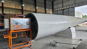
Being a test blade, the D78's composite skin surfaces were all unpainted at the time of the factory visit, providing a chance to see details such as the different core materials sandwiched within the structure. Remarkably, bonding seams between adjoining components were hardly visible. The blade itself consists of four sections viewed from the blade root, with individual lengths of 30, 25, 10 and 13 metres each. The 13-metre tip section is made in an entirely different process to further reduce weight, and has an in-house developed anti-erosion layer, called BladeShield, fused within the component along the leading edge.
Customisation
The intermediate section - ten metres on the D78 - can vary in length, producing customised rotor diameters using a "platform approach" with similar mould tools and blade assembly facilities. This keeps blade-length customisation costs low, enabling more owners to optimise the output of individual turbines and wind farms. It also means that the company can respond quickly and flexibly to market demands.
Blade assembly starts with the root section — composed of five "semi-flat" 72-degree segments for easy transportation and manufacture, and each incorporating the company's patented blade-root design (see box, overleaf). Each segment is bolted to a heavy-duty steel ring with a rotor hub bolt circle, according to Botha. "We apply a unique, self-aligning over-lamination method for the precision joining of these segments and other blade shell sections," he says.
The process continues with lining up the jigging tools on a level floor space and putting in all matching lower shell sections. This is followed by lowering-in the pre-assembled spar box (see box, overleaf), and the structure closing with the upper shell sections.
At the time of my visit, the technicians had yet to fix the separately moulded, high-performance blade tip, which includes a machined copper outer tip forming an integral part of the blade's lightning protection system. The D78 will then be shipped from New Orleans harbour to the UK's Offshore Renewable Energy Centre's research and testing facilities, where it will undergo five months of static and dynamic fatigue testing to all requirements for type certification.
Cost-cutting mission
Blade Dynamics, founded in 2007, started work on the D78 blade late in 2012, winning £15.5 million (€21.5 million) in development from the UK's Energy Technologies Institute (ETI), a government and private company research partnership, following a competition for proposals to "address the current high generating costs of the UK's offshore wind energy sector".
The project was designed to demonstrate that the company's overall approach could reduce (offshore) turbine lifecycle-based cost of energy (CoE) compared with current blade designs, and be adopted for even larger blades in the future.
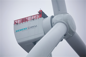
"Siemens Wind Power provided the load set and the critical dimensions for its 75-metre B75 blade, that is currently being used for the 6MW SWT-6.0-154 turbine," says Botha. "The D78 design was an iterative process, with Siemens providing loads analysis and feedback on Blade Dynamics blade designs for the turbine. We designed a longer blade with a carbon spar using our own aerodynamic design."
The initial development phase lasted around a year and was used to adapt and refine technologies developed for the 2MW D49 programme, scaling-up to 6MW. This D49 blade originated from 2009 and was aimed at increasing the power-generating potential of AMSC's 2MW turbine model, fitted with 45-metre glass-fibre blades, each weighing 9 tonnes. The D49 offers a blade length of 49 metres, weighing only 6.15 tonnes, with an unchanged loads spectrum and only +/10kg mass variation "out of the mould".
As long as possible
"The D78 design phase started in late 2013 and the main goal was to develop a new blade, as long as possible, with a comparable loads spectrum," says Botha. "The main outcomes were a 78-metre blade with comparable aerodynamic loads but 20% reduction in fatigue loading due to lower blade mass. The Siemens B75 blade is made of glass-fibre reinforced epoxy and weighs about 25 tonnes. The mass of our three-metre longer blade is approximately 22.5 tonnes, a saving of 10% by applying a different structural design, including carbon incorporated in the structural spar boxes. The 8% extra rotor-swept area translates into 2.5-3% higher annual energy production and potentially 3-5% CoE reduction too, despite the use of expensive carbon."
Botha stresses that the modular blade technology and D78 development experiences can be reapplied in both smaller and larger blades, offering major logistical cost savings and other benefits. The first category includes next-generation blades for the latest lowand medium-wind 3MW-plus onshore turbines, and the new 3.6-4.5MW onshore class.
As part of ETI's very long blade project, Blade Dynamics has also explored how D78 technology insights could be reapplied to even larger future blades. It resulted in a design project of a 103-metre blade for 10MW turbines, modelled around the open-source Danish Technical University 10MW turbine platform. "This required multiple innovative technology developments, and initial indications are that such a blade could be built using Blade Dynamics technology with a mass in the order of 35 tonnes, similar to the latest conventional-design 80-83-metre blades," says Botha. "With the D78 almost ready, we asked our UK and US teams whether they thought a 100-metre-plus blade that builds on similar design and manufacturing principles would be feasible. Their answer was unanimously positive.
DISTINGUISHING FEATURES — PATENTED BLADE ROOT AND INNER SPAR TECHNOLOGIES

Final touch… The 13-metre blade tip
With conventional blades, the blade root comprises a thick-wall circular section integrated into the shell's structure. Blade bolts are commonly assembled by a "T-bolt" or "Ikea" method; multiple holes drilled into the root circumference for nut placing, and the same number drilled vertically inside the root's wall section for the bolts.
Due to imperfect loads transfer, such blade roots have to endure high local composite material stresses. The Ikea-solution also inherently requires substantial inter-bolt spacing, which limits the number of bolts for a given root circle diameter.
"The root of (our) blade is very lightweight and has wall thickness variation, giving it a corrugated appearance, similar to a shotgun belt," says Botha. "The thicker sections are formed around high-performance root inserts, which transfer very high mechanical loads in a small space while minimising stress concentration.
"The key to this is that the composite root inserts are designed around a helical metallic component that they can be directly bolted into, like any other root," he adds.
"This patented insert has an outer spiral design providing optimised loads transfer to a tapered glass-fibre reinforced epoxy mantle. Our solution creates the design space to carry longer blades, with higher root bending moments, without increasing root diameters, and also to reduce mass and, therefore, the cost of materials in the root area," says Botha.
The load-carrying lightweight spar box assembly incorporates pre-consolidated multiple carbon layers extending along the spar box. In a finished blade the carbon is right underneath the shell inner surfaces. This provides an analogy to conventional blades by having carbon fibres integrated in the structurally optimised stiffness and strength characteristics of the blade.
Spar box design
A clever design feature is that the spar box assembly in ready form consists of two permanently bonded lightweight spar boxes in parallel. Spar box maximum height is reached where the spar box starts inside the blade root and gradually narrows towards the tip.
While the individual spar box size and shape are identical, their relative positioning towards each other enables them to follow the aerofoil shape and twist exactly. Because the spar box assembly carries the main structural loads, the outer shell elements built predominantly in glass-fibre reinforced composite serve as aerodynamic cladding mainly, but they also contribute to the blade's structural integrity.
THE LONG ROAD FROM PROTOTYPE TO PRODUCTION - BY SHAUN CAMPBELL
The path from prototype to production for very long rotor blades is rarely short or straightforward. And if that applies to blades built using well-tried and tested methods and techniques, it is even more true for a design as radically different as the D78. Understandably, then, Blade Dynamics is reluctant to provide a timescale for when blades built to this design and manufacturing process could be expected to enter serial production.
As a general rule of thumb it takes between three and four years to take a blade from the drawing board to type approval, with at least a year of static and fatigue tests. But Blade Dynamics should expect a rather longer testing and qualifying programme before it can satisfy potential customers and, most importantly, insurance providers, that its new system works.
If the prototype blade proceeds well through its static tests, the next step would be to put a full rotor set on an appropriate offshore turbine. It is hard to imagine that being achieved before 2017. Assuming again that those tests go well, you might expect that serial production could start in 2019.
Upcoming events:
“uåX˜äŠÊ˜·³Ç Blade Inspection, Damage and Repair Forum, 28-30 September 2015, Copenhagan
.png)

.png)